We often get queries from customers about traceroute oddities in an MPLS world. This document is intended to explain the difference between an IP traceroute and an MPLS traceroute in reasonably simple terms.
IP Traceroute
We can't talk about MPLS traceroute until we've discussed IP traceroute.
Every IP packet has a field in its header called the "TTL" value. By placing a "lifetime" on each packet, the TTL value is supposed to make the network discard packets which are involved in routing loops.
The system which transmits each packet initialises the TTL to a value which indicates the maximum number of times the packet is allowed to pass through routers before it's considered too "old" to survive. Each router the packet passes through will decrease the TTL value; the router, which makes it reach 0, discards the packet and sends a message back to the packet's originator to say it never reached its destination.
Traceroute takes advantage of this functionality by deliberately sending packets with very low TTLs.
Lets say you're in Perth and you want to traceroute to a router in Sydney, via Adelaide:
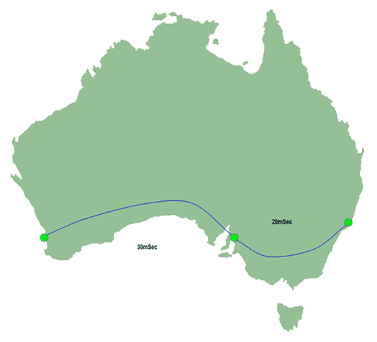 |
| Figure 1: IP Traceroute Path |
When you issue the "traceroute" command to your computer, it will attempt to send a packet from Perth to Sydney with the TTL set to "1". That packet will be sent to Sydney, via Adelaide.
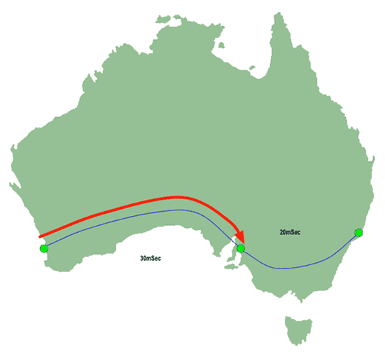 |
| Figure 2: IP Traceroute - First Hop |
As described above, each router which encounters the packet will decrement the TTL. In this instance the router in Adelaide will be the first one the packet encounters, and, because the packet's TTL is "1" that means the Adelaide router will decrement it to 0. The usual response when this happens is for the Adelaide router to send a message back to you in Perth to say it has discarded your packet:
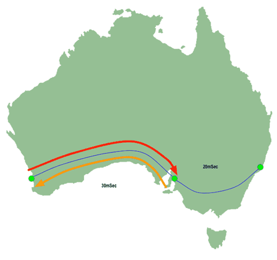 |
| Figure 3: IP Traceroute - First return packet |
Your traceroute tool will look at the amount of time which has passed between sending the probe and receiving the response from Adelaide. In this case it'll be 60 mSec, because the probe packet has spent 30 mSec crossing the Nullabor Plain from Perth to Adelaide, and the response packet has had to spend another 30 mSec getting back. So traceroute will report something like this:
1 adelaide 60ms 60ms 60ms
Next, it sends another probe packet to Sydney, this time with the TTL set to 2. On this simple network, that's enough to allow the packet to reach its destination.
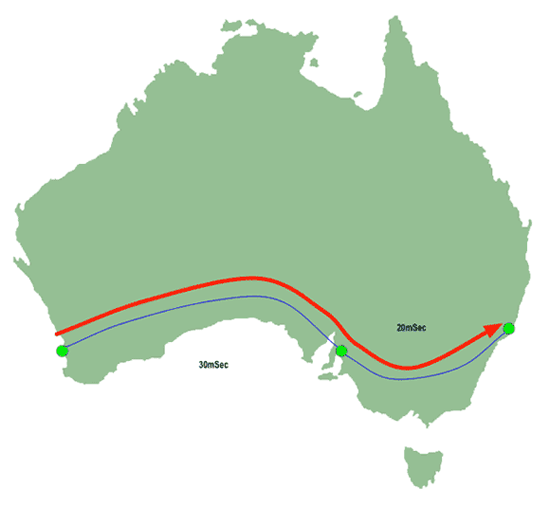 |
| Figure 4: IP Traceroute - Second hop |
The Sydney router responds:
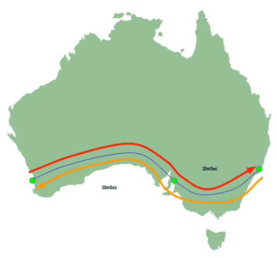 |
| Figure 5: IP Traceroute - Second return packet |
…and traceroute calculates the latency (30mSec across the Nullabor to Adelaide, 20mSec from Adelaide to Sydney, then the same again to get back to Perth again) and reports the response:
2 sydney 100ms 100ms 100ms
So the total traceroute output will have looked something like this:
1 adelaide 60ms 60ms 60ms
2 sydney 100ms 100ms 100ms
MPLS Traceroute
How does this picture change in an MPLS environment?
The key difference between IP switching and MPLS switching is that MPLS pre-calculates the path a packet takes before the packet is ever transmitted. Once the pre-calculated path is formulated, the packet is more or less committed to following it.
Furthermore, the intermediate routers try not to waste their CPU time calculating paths for packets which don't involve them. So, for instance, the Adelaide router won't bother working out how to get packets between Perth and Sydney, even though it's in the middle of the path: it's up to the Perth router to work out that it gets to Sydney via Adelaide, and for the Sydney router to work out the Perth path, and Adelaide just sits in the middle passing packets, trying to stay as stupid as possible, avoiding any particular knowledge about how the various network endpoints are talking to each other.
When an MPLS-switching router generates one of the messages used to indicate a network error, it punts the error message along the same path that has already been calculated to carry the packet which caused the error. This affects traceroutes, because the messages which say, "Your TTL is zero so I dropped a packet" fall within that class of packets.
So lets see what happens when Perth traceroutes to Sydney on an MPLS network:
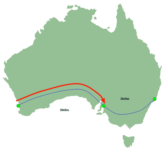 |
| Figure 6: MPLS Traceroute - First hop |
Our Perth user has sent a traceroute probe to Sydney with a TTL of "1". The packet has reached as far as Adelaide, which has dropped the TTL to 0 and emitted a "I can't deliver your packet" message intended for Perth. But because Adelaide is MPLS-switching, it sends that message along the path which has already been pre-calculated for the packet which was dropped!
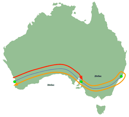 |
| Figure 7: MPLS Traceroute - First return packet |
So that means the traceroute response packet continues along the path to Sydney, whereupon the Sydney router examines its destination address, works out it's intended for Perth, and sends it back. Eventually the packet gets back to Perth, which calculates the response latency and reports something like this:
1 adelaide 100ms 100ms 100ms
Then Perth emits another probe, this time with a TTL set to "2", which manages to get all the way to its destination in exactly the same way it would if it was on a non-MPLS network:
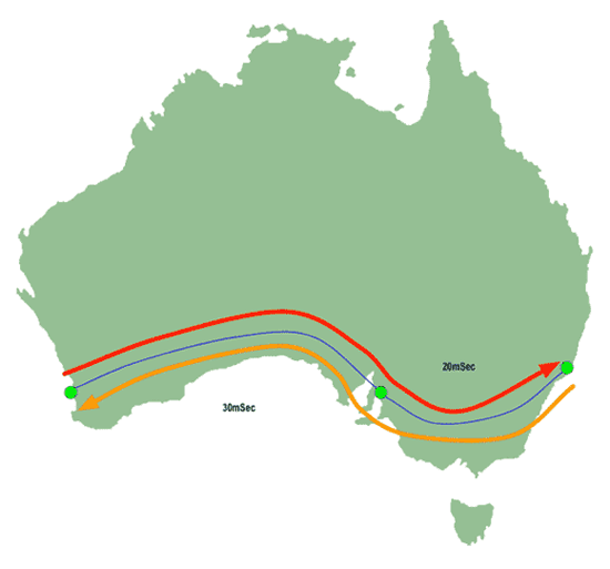 |
| Figure 8: MPLS Traceroute - Second return packet |
So the traceroute the Perth user sees looks like this:
1 adelaide 100ms 100ms 100ms
2 sydney 100ms 100ms 100ms
"Oh my god!" the Perth user says, "Adelaide isn't supposed to be 100mSec away! That must mean the link to Adelaide is congested!"
But, no, it just means the response from Adelaide is going to Sydney before being sent back to Perth. It's travelling several thousand kilometres of extra distance, and consequently takes longer to arrive. There is no real problem here, it's just a cosmetic side-effect of the way ICMP error messages are treated by MPLS-switching routers.
The most obvious visual indication of this occurs on our International network, where folks who traceroute to, say, Google might find that an extra 180 mSec of latency magically appears between two Australian hops inside our network:
traceroute to www.l.google.com (66.102.7.104), 64 hops max, 40 byte packets
 1  gi0-2-700.cor1.adl2.internode.on.net (150.101.0.137)  1.594 ms  1.176 ms  1.002 ms
 2  gi0-3.bdr2.adl2.internode.on.net (203.16.212.145)  1.204 ms  1.507 ms  1.274 ms
 3  pos2-0.bdr1.syd7.agile.on.net (203.16.212.33)  179.499 ms  179.609 ms  180.124 ms
 4  pos1-2.bdr1.sjc2.agile.on.net (203.16.213.33)  181.039 ms  180.204 ms  180.484 ms
 5  eqixsj-google-gige.google.com (206.223.116.21)  176.824 ms  175.822 ms  176.013 ms
 6  66.249.95.69 (66.249.95.69)  181.502 ms  181.841 ms  181.868 ms
 7  66.249.94.226 (66.249.94.226)  181.524 ms  182.476 ms  181.178 ms
 8  72.14.233.129 (72.14.233.129)  181.650 ms  181.094 ms  181.774 ms
 9  216.239.49.142 (216.239.49.142)  183.286 ms * 216.239.49.146 (216.239.49.146)  183.024 ms
10  66.102.7.104 (66.102.7.104)  181.497 ms  181.792 ms  181.986 ms
Hop 3, which is ostensibly the link between Adelaide and Sydney, looks atrocious! 180mSec just to get from Adelaide to Sydney! Something must be desperately wrong!
But, no, what's happening is that the ICMP response from Sydney is being sent to San Jose and back before going back to Adelaide, in precisely the manner described above.
This can be verified by pinging intermediate hosts. A ping directed at bdr1.syd7 looks like this:
ping -c 5 bdr1.syd7
PING bdr1.syd7.internode.on.net (150.101.197.127): 56 data bytes
64 bytes from 150.101.197.127: icmp_seq=0 ttl=253 time=26.276 ms
64 bytes from 150.101.197.127: icmp_seq=1 ttl=253 time=26.234 ms
64 bytes from 150.101.197.127: icmp_seq=2 ttl=253 time=26.239 ms
64 bytes from 150.101.197.127: icmp_seq=3 ttl=253 time=26.107 ms
64 bytes from 150.101.197.127: icmp_seq=4 ttl=253 time=26.223 ms

--- bdr1.syd7.internode.on.net ping statistics ---
5 packets transmitted, 5 packets received, 0% packet loss
round-trip min/avg/max/stddev = 26.107/26.216/26.276/0.057 ms
…which is clearly not 180mSec, and equally clearly not congested.
A more tech-heavy presentation of this same info is on Cisco's website here:
The Traceroute Command in MPLS

